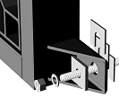
Slotted shims, stainless chem-bolts and compressible gasket material are supplied
with each valve.
See below for full mounting instructions.

We recommend the use of chemical anchor bolts and a compressible gasket, when bolting to concrete structures. The bitumen-impregnated 'Compriband' material supplied by Batescrew, compresses from 50mm to 10mm, giving an excellent seal against a concrete surface.
The slotted shims provided, are placed behind the
mounting cleats. The valve is clamped firmly against these, while
still leaving approximately 10mm gap for the gasket.
Permanent distortion and leakage may be caused by incorrect
use of the shims. The following procedure will avoid distortion of
the valve body.
TO DETERMINE CORRECT NUMBER OF SHIMS This is best done by placing the valve against the headwall, without a gasket, and checking the number of shims required to just fill any gap at each cleat. Write this number on the cleat. Add three more shims to this figure, at each bolt location, when finally mounting the valve and gasket.
CHEMICAL ANCHOR BOLTS. All valves, from 300mm to 1800mm, may be secured with 12mm bolts. With each valve, we supply all necessary chem-bolts, a 14mm masonry drill and a chem-bolt data sheet. The normal chem-bolts supplied are M12 x 160 Stainless. If used as recommended, these will protrude 50mm from the headwall (a 14mm hole is drilled 110mm into the masonry). This will require that the gasket be manually compressed somewhat, to initially get nuts onto the threads.
A common practice is to allow the two centreline bolts to protrude 75mm, enabling initial compression with two nuts. This system has given satisfactory results.
(It is also common practice, using M12 x 160 bolts, to allow them to protrude from the concrete sufficiently to get nuts onto all of the threads, when the 50mm gasket is in place. It should be noted that this does not allow the bolts to enter as deeply into the resin-filled hole, as specified by the maker's data sheet. Although we are unaware of any failures, we are not able to endorse this practice.)
LONGER BOLTS may be needed, when fitting to an irregular headwall. With this in mind, the condition of headwalls should be checked, before commencing the job, and ordering suitable bolts with the valve. Permissible irregularity of headwall surfaces is ± 3mm per 3m of face.
DRILLING LOCATIONS for bolt holes are commonly marked through a valve body, removing the valve to drill and clean the holes and set the anchor bolts. Ample clearance has been allowed in the cleats, to accommodate slight inaccuracies in masonry drilling.
GASKET. With each valve, we supply gasket material, in two metre strips, of 50mm by 50mm cross section. Also a quantity of contact adhesive. Prepared strips of gasket are glued to the flat back face of the valve, around the circular spigot (not glued to the spigot). When joining gasket, it is necessary to scarf each end at 30°, cutting in a direction which will bring the joint faces tightly together in compression.
IRREGULAR or DAMAGED headwall surfaces should be repaired, preferably with commonly available epoxy mortar. Flatness tolerance is ± 3mm per 3m.
SPIGOT. A short spigot protruding from the rear is a structural element of the valve, providing rigidity and support to the stainless seat. It has a slight clearance within the inner wall of the pipe and is not intended to be grouted. The presence of the spigot offers negligible resistance to flow.