|
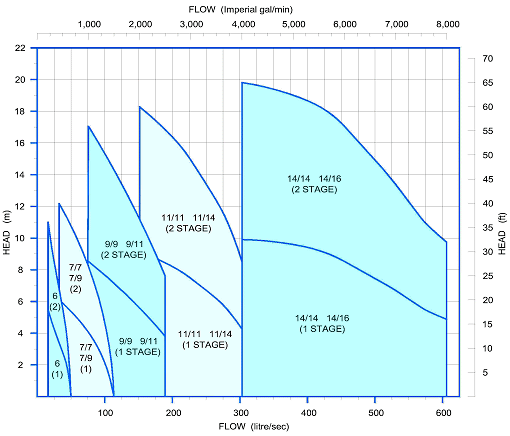
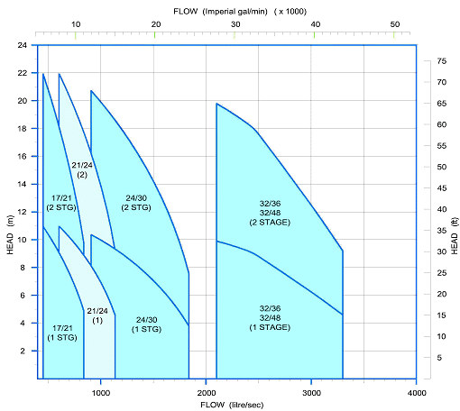
Charts
of HEAD and FLOW RATE for single and two stage Batescrew Axial Flow Pumps.
The curves below show the Head / Flow Rate for each
pump in the axial flow range.
When two pump sizes are capable of performing at given head/flow, a comparison of running costs is calculated by comparing the
efficiency levels of the impellers available (see Impeller
Performance Curves). For most pumps, Batescrew have available
more than one impeller, of slightly differing characteristics. Our
Technical Services dept. will assist with impeller selection.
For any given task, running and maintenance costs of the larger of two pumps will
normally be lower.
The tables below give values for single and two-stage pumps. More
impeller stages may be added to a pump for increased total head, the
number of permissible stages being governed by the particular impeller
chosen, in some cases up to eight stages. The maximum number of
stages is quoted for each impeller, at the head of it's Impeller
Performance Curve.
Note: Each
additional impeller stage directly multiplies the head achieved and power
consumption but has no appreciable effect on flow rate.
|


