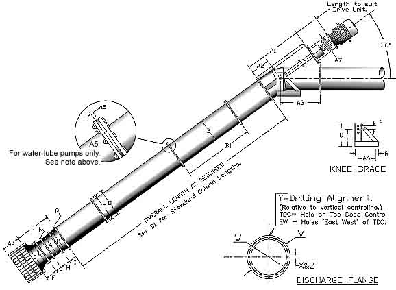
Axial Flow Pumps. Angle Application.
9/9 Pump
Dimensions.
click here for Extended Drive Column.
| Note: On water lubricated pumps, the length of column sections (B1) is limited to 1.22 metres, to allow for inclusion of a Centre Bearing Holder (A5) between each flange. Bearings are required at each column flange, except the lowest, which is adjacent to the bottom assembly. If the topmost column section is shorter than 1.22 metres, a bearing will not be required under the Discharge Head. |
|
|
|
ITEM |
mm |
|
ITEM |
mm |
|
ITEM |
mm |
|
A |
Impeller
Diameter |
228.6 |
M |
Stator
Flange PCD |
279.4 |
Y |
Disch
Bolts EW or TDC |
(TDC) |
|
B |
Column
Diameter |
228.6 |
N |
Stator
Flange Hole Dia. |
14.3 |
Z |
Disch
Flng No of Bolts |
8 |
|
C |
Bellmouth
Diameter |
381 |
O |
Column
Flange OD |
304.8 |
A1 |
Head
Height |
890 |
|
D |
1
Stage Length |
262 |
P |
Column
Flange PCD |
279.4 |
A2 |
Disch
C/L Height |
245 |
|
E |
2
Stage Length |
596.6 |
Q |
Column
Flng Hole Dia. |
14.3 |
A3 |
Flng
Face to Vert C/L |
685 |
|
F |
Bellmouth
Length |
127 |
R |
Knee
Brace Length |
457 |
A4 |
Strainer
Length |
190 |
|
G |
Running
Ring Length |
95.3 |
S |
Pivot
Adjustment Crs. |
64 |
A5 |
Centre
Brg Holder Thkns |
12.7 |
|
H |
Stator
Length |
139.7 |
T |
Pivot
Height |
355 |
A6 |
Knee
Brace Bolt Crs. |
355 |
|
I |
Adaptor
Length |
- |
U |
Knee
Brace Height |
457 |
A7 |
Drive
Column Dia. |
152.4 |
|
J |
Impeller
Shaft Length |
812.8 |
V |
Discharge
Flange OD |
311.2 |
A8 |
Extension
Gland Stool |
381 |
|
K |
Impeller
Shaft Diameter |
31.75 |
W |
Discharge
Flange PCD |
279.4 |
|
|
|
|
L |
Stator
Flange Diameter |
304.8 |
X |
Dischg
Flng Hole Dia. |
14.3 |
|
Knee
Brace Channel |
4x2” |
|
B1
Standard Column Lengths |
Water
Lube |
305 |
610 |
914 |
1219 |
|
||
|
Oil
Lube |
305 |
610 |
914 |
1219 |
2438 |